Jo Engine
What is it ?
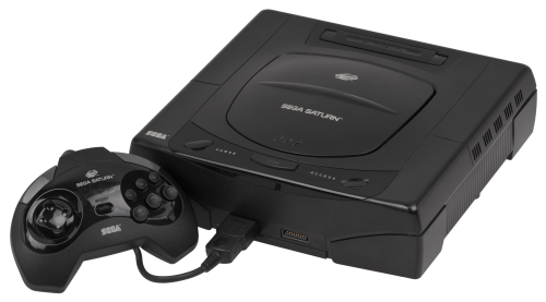
Jo Engine is an open source 2D and 3D game engine for the Sega Saturn written in C under MIT license.
It allows to develop game easily without extensive knowledge in embedded development.
And... games run on emulator and also on the original system !

Features
- File System (CD)
- Load 3D mesh
- Loading sprite in TGA, 15 bits image or raw from the CD
- Sprite animation
- Tileset & Map
- Audio (CD & PCM)
- Gamepad
- Parallax Scrolling
- Mode7
- Etc.
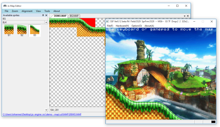
The Jo Engine has his own map editor:
Example : Draw a sprite loaded from the CD
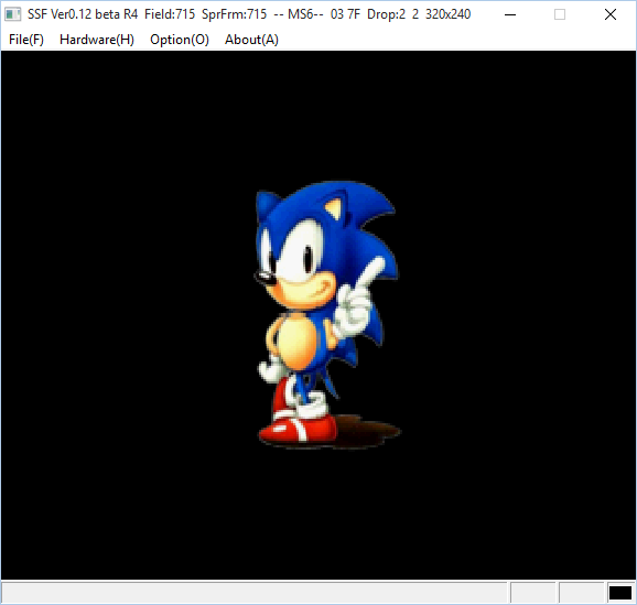 #include <jo/jo.h>
void my_draw(void)
{
jo_sprite_draw3D(0, 0, 0, 500);
}
void jo_main(void)
{
jo_core_init(JO_COLOR_Black);
jo_sprite_add_tga("TEX", "A.TGA", JO_COLOR_Transparent);
jo_core_add_callback(my_draw);
jo_core_run();
}
About me
 I'm Johannes Fetz, I live in France and I work at Eureka-Technology. I'm also a teacher in Etna (C language, Windows, Unix, MacOS, POO).
The Sega Saturn is above all to me full of memories with my friends in middle School. This is also my favorite console even if its marketing was a failure. I think it's the intrinsic atmosphere of some games like Panzer Dragoon Saga which seduced me. This is one of the reasons I wanted to develop on that console deemed to be one of the most complicated platforms of all time with the PS3.
Unfortunately the rumor was based ...
In fact, Sega Saturn console is a difficult to understand (see documentation). This is why there are only very few homebrew and most emulators wasn't stable for a long time.
That's why I decide to create a simple game engine so that everyone can develop on the Sega Saturn.
Special thanks
- The Rockin'-B, for is job and tutorials
- Sega
- Everybody who supports me on Youtube, SEGASaturno, segaxtreme.net, sega-16.com, gamopat-forum, segasaturnshiro.eklablog.com, Segasaturnshine
Copyright © 2012-2023 Johannes Fetz, All rights reserved.
